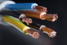
We return to our series on the anatomy of a conductor to discuss the basic factors considered by the electrical professional in sizing the conductor. Anatomy of a Conductor Part 1
The conductor size, whether in AWG or MM2, is dependent on the amount of current that will travel through it for delivery to the electrical load. A threshold issue is the fact that not all current (Amps) are "created" equal. This means that for the same electrical load (kVA, kW or HP), the current (Amp) value will be different depending on (1) the system voltage, (2) the system phase and (3) the equipment's number of poles (single, two or three poles).
To start, the electrical professional first converts the electrical load (kVA, kW, or HP) to current (Amps), see NEC 210.19, taking into consideration the noted initial factors: (1) system voltage, (2) system phase and (3) the equipment's number of poles (single, two or three poles).
Applying the engineering equation for power, the electrical professional then obtains the base current value. Just to complicate the issue, if the system voltage is different than the equipment utilization voltage (EUV), then the calculation of the base current value must be based on the EUV. This change requires the placement of a transformer to convert the system voltage to the EUV. And then, be certain to consider the branch circuit voltage limitations applicable to the EUV. See NEC 210.6.

Once the size of the conductor is calculated and the number of conductors determined, the electrical professional continues by calculating the size of the conduit containing these current carrying conductors. See NEC Chapter 9, Table 1, Annex C1 through C12A. When the base current value is determined, the electrical professional then proceeds through the following sequence of calculations to determine:
(1) the overcurrent protection device (OCPD), see NEC Article 240
(2) the ground conductor, see NEC Article 250
(3) the voltage drop, see NEC Article 215 NEC
With these basic calculations completed, the electrical professional then applies the remaining factors: continuous and non-continuous load, coincidental and non-coincidental load, temperature limitation, temperature correction factor, adjustment factor (number of conductors in a raceway), special conditions/applications (current carrying conductor and tap rule), ground electrode conductor, conductors in parallel, and load types (receptacle, lighting or air conditioning).
The discussion of the complex requirements of the conductor will continue in our series on the conductor.Resources


