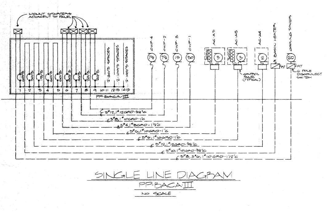
1 Line Diagram: Existing Conditions from Record Documents
Designing for renovation is easy...let's go through the steps.
A PowerCalc user with an engineering consulting firm recently sent us this 1 Line Diagram documenting existing conditions at a meeting facility in Alabama. His question: how to modify just 6 of the 9 existing circuits in a power panel (PP).
Above is the 1 Line Diagram of existing conditions provided by the user. For purposes of this article, we input these values into PowerCalc and 1st, creating the model of the 1 Line Diagram for existing conditions. See below:
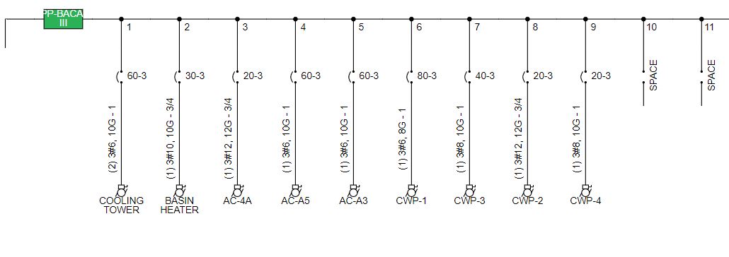
1 Line Diagram: Existing Conditions as modeled in PowerCalc
The 3 unchanged circuits were to remain in their AsBulit state. As an example, CKT PP-3 currently feeding a 2 HP AC-A4 (Air Conditioning # 4A), 20 A-3P OCPD, 3#12 AWG. 1#12 GND, in 3/4" conduit.
The way to design a renovation with PowerCalc:
1. Recognizing that not all renovations are a total demolition, this response distinguishes between existing loads that remain As Is in the final project and those loads that will be modified to accommodate the new design.
2. First, create a Project file: Project Name_Existing. The use of the "Existing" label organizes your design files. Then, input all existing conditions in the project's panels.
For equipment, remember to use a separate Building Equipment (BE) calculation / worksheet for each piece of equipment such as a pump, an HVAC unit, or an elevator. The practice of a separate BE worksheet for each piece of equipment makes it easy to update circuits quickly throughout the design process.
3. Once all existing conditions have been input, then go to the Related Projects button. Find Project Name _Existing, then under Actions, click on Save As to create a second file. Save this new file as Project Name _Modified.
4. Keep both files. You now have 1 file documenting existing conditions and a new second file that reflects your modified design.
Go to each circuit in the Project Name_Modified and update the design by changing each individual branch circuit.
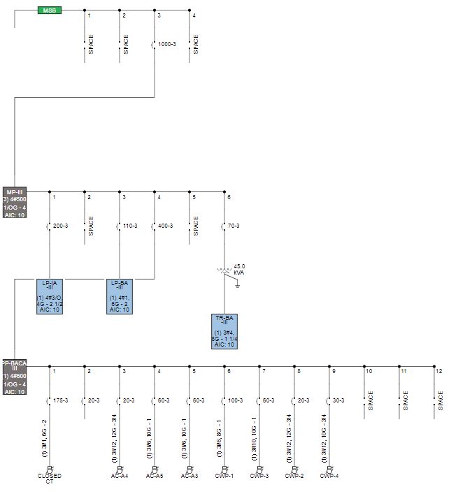
1 Line Diagram: Modified for Renovation by PowerCalc
5. The second part of the user's question on renovation was: how to override PowerCalc's default values. To override, go to Building Equipment worksheet AC-4A, and in the footer find the FEEDER region. In this region are 5 cells titled AUTO.
These cells can be changed from the automatically calculated NEC values, to the size you determine as an electrical professional to use for your project. Also in the FEEDER region, the user can enter the actual conductor length. Then, PowerCalc will also automatically calculate the Voltage Drop (VD) and Short Circuit Current (S2C).
6. Then, repeat this process in the Enclosed Circuit Breaker and the DISCONNECT regions to override PowerCalc's automatic NEC calculated values so that the values reflect existing conditions.
Designing renovation projects with PowerCalc, is as easy as new construction.

And remember, we have a free demonstration on the first Friday of each month: FREE Demo, Friday May 1st at 12 EST Hope you will join us!
Thank you for your support! Stay well.